In this section a short description of the project objectives and technical activities performed is reported.
Robots and Volcanoes
From as early as Greek and Roman times volcanic activity has been well recorded and reported because of the huge impact that eruptions have on human activities. Ancient populations lived in awe of unpredictable eruptions, suffering loss of human life as well as huge damage to their towns and lands. As a result, people began to venture near to active volcanic vents in order to understand volcanic phenomena. The philosophers Empedocles and Pliny the Elder observed volcanic eruptions too closely and paid for their thirst for knowledge with their lives. Since then many scientists and observers studying eruptions have been killed or suffered serious injury. In the last decade alone, due to both the unpredictability and magnitude of volcanic phenomena, several volcanologists have died surveying eruptions [1],[2][3].
At this time 1,500 volcanoes on Earth are potentially active, approximately 500 of which have been active during the 20th century and about 70 are presently erupting. At the beginning of the third millennium, 10% of the world population live in areas directly threatened by volcanoes, without considering the effects of eruptions on climate or air-traffic for example. About 30,000 people have died from volcanic eruptions in the past 50 years, and billions of euros of damage has been incurred. Significant advances in eruption prediction and forecasting have been made in recent years, partly as the result of studies of the major volcanic eruptions at Mount St Helens (USA) in 1980, Nevado del Ruiz (Colombia) in 1985, Pinatubo (Philippines) in 1991 and Unzen (Japan) in 1991. Over the same period significant progress has been achieved in the understanding of how volcanoes work. This is especially true for a few volcanoes in which particular effort has been made. This is the case for Etna, Vesuvius and Vulcano (Italy), Santorini (Greece), Teide (Spain), Furnas (Portugal), Sakurajima (Japan), Merapi (Indonesia), Popocatepetl (Mexico), however many other volcanoes are not sufficiently monitored and a catastrophe like that of Nevado del Ruiz can occur again.
Such reasons together with recent advances in robotics have inspired a new EC project named ROBOVOLC with the aim of designing and building a mobile robot for volcanic exploration whose activities started in March 2000 [4]. The final partnerships includes two Universities (Università degli Studi di Catania, Italy and University of Leeds, U.K.), two industrial organisations (Robosoft, France and BAE Systems, U.K.) and two research organisations who provide expertise in volcanology and cartography: the Istituto Nazionale di Geofisica e Vulcanologia, Italy and the Institute de Physique du Globe de Paris, France.
A major aim of this project is to minimise the risk to vulcanologists and technicians involved in work close to volcanic vents during eruptive phenomena. It should be noted that observations and measurement of the variables relating to volcanic activity are of greatest interest during paroxismal phases of eruptions, which unfortunately are also the periods of greatest risk to humans.
Vulcanologists have identified that a volcano exploration robot should be able to carry out a number of key operations, the most important being the ability to:
- approach an active volcanic vent
- collect samples of volcanic eruption products
- collect other physical and chemical data
- survey close to vent openings
Volcanic gas is quickly contaminated by the atmosphere and is thus empirically worthless to collect for analysis far from the eruptive vent. As this environment is extremely dangerous for humans this is a task suitable for a robust rover robot which can collect more reliable samples and data, close to their volcanic source.
Sites of interest include lava flows, ash and spatter cones and large ground fractures; in general these surfaces are very rough and disconnected and occur close to, or inside, volcanic craters. The ground often has a steep gradient and unstable surface due to loose rocks and sliding materials, therefore the robot needs a sophisticated assembly to move safely and surely. Sometimes the location being investigated will be unexplored so a video link between the rover robot and the operator is essential for safe navigation. A ranging system is useful for both driving and measurement purposes. Finally an efficient data link is required to control the rover and to download collected data.
In order to achieve these goals, new algorithms and software for autonomous and semi-autonomous navigation of a robot in unstructured environments have been developed. For autonomous navigation, we intend that the robot be capable of reaching a given position in the volcanic area autonomously and automatically perform the tasks required to perform the measurements. In the case of very difficult or dangerous situations (e.g. proximity to lava flows or fissures), the robot will be tele-operated and able to act in a semi-autonomous way. In this case, by using a specifically designed user interface, an operator will be able to drive the robot effectively from a safe location. For semi-autonomous use, we intend that the robot will have the capability of autonomously selecting and executing some sub-tasks, e.g. position and speed of individual wheels, measurement operations, etc.
Data collected by the robot will be used primarily to enhance knowledge of volcanic processes. For example close field data collected by the robot during eruptions will be used as input data for computer simulation of volcanic activity to improve forecasts for long-lived volcanic phenomena such as lava flow eruptions.
Go Back to Menù
Past volcano robot projects
The first stage of the ROBOVOLC project involved the analysis of the state of the art in rough terrain robotics. If attention is concentrated on recent projects with the specific objective of volcanic exploration only a few systems have been developed. However it should be observed that following the successful results of the Sojourner robot on the surface of Mars, many new robots have been designed for planetary exploration. In many cases these robots have been tested in volcanic environments, because of the strong terrain similarities.
In particular this section reviews three distinct volcano robot projects which involve a legged, a wheeled and a flying robot, all of which were tested in volcanic environments. The complete results of all the systems review has been reported in the Deliverable D2.a and partially published in [5].
Dante II
Dante II is a multi-legged frame walking robot designed by NASA and Carnegie Mellon University to investigate live volcanoes and test robotic technology [6],[7],[8],[9]. The robot is a framewalker with eight pantographic legs arranged in two groups of four, on inner and outer frames. A tension-controlled tether was connected to Dante II, to maintain stability and to allow rappelling on steep slopes [10].
In 1994 Dante II underwent a trial exploration of Mount Spurr volcano in Alaska. For more than five days the robot explored alone in the volcano crater using a combination of supervised autonomous control, and tele-operated, control. The robot travelled one-quarter of its 165-m descent autonomously, relying only on on-board sensors and computers to plan and execute its motion. The terrain was very rough including crossing 1-m boulders on ash-covered slopes, navigating areas of deep snow, ditches and rubble. The robot measured the gas composition of several large fumarole vents [7]. However while climbing out of the crater, Dante II lost stability and fell on its side thus ending its mission. The Dante II/Mt. Spurr expedition was considered a success because of the amount of data and experience that was accumulated. Dante II was successful in retrieving data from a very harsh environment such as might be expected on other planets. This trial gave NASA valuable experience in determining what improvement considerations would be needed for future robotic missions.
Marsokhod
The Marsokhod rover is an all terrain vehicle developed by the Mobile Vehicle Engineering Institute (VNIITransmash) in Russia for planetary exploration [11]. The chassis (100cm wide, 150cm long, 35kg unloaded mass) consists of three pairs of independently driven titanium wheels joined together by a three degree of freedom passively articulated frame. This design enables the rover to conform passively to very rugged terrain. The amplifiers, motors and batteries are mounted inside the wheels to provide a very low centre-of-gravity. The robot can travel at speeds up to 12 cm/sec and can traverse obstacles up to 30 cm high and slopes up to 45°. The duration of operation with batteries is approximately 6 hours.
The Marsokhod robot, originally designed for Mars exploration, has been extensively tested in volcanic environments such as in Kamchatka, Russia (1993), Amboy crater in California (1994) and Kilauea Volcano in Hawaii (1995). Kilauea Volcano was selected primarily for its great diversity of geological features similar to those expected on Mars and the Moon [12].
Yamaha Helicopter
Yamaha has been involved in a project for the surveillance of the Mt. Usu Volcano in the Hokkaido region of Japan. For this purpose a special version of the unmanned helicopter RMAX has been developed. Due to the large distances of operation an autonomous flight system has been developed and the cruise autonomy of the helicopter increased to 4km. In April 2000 the helicopter, equipped with four CCD cameras, was successful in performing several surveillance missions observing the hazards caused by volcanic sediment and debris flow [13].
Requirements and specifications
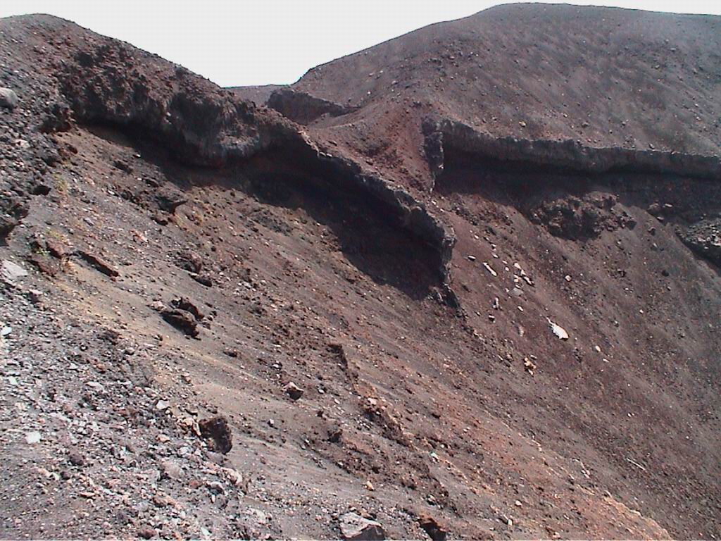
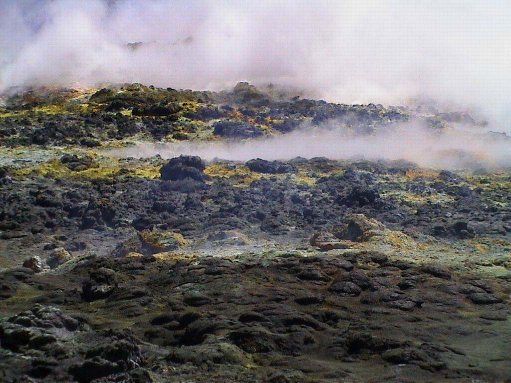
Technical visits to volcanic sites (Etna, Stromboli and Vulcano) were organised in the spring-summer 2000 and detailed discussions were carried out with vulcanologists, in order to investigate the requirements of a system. An important consideration that was immediately apparent was the extremely rough and difficult volcanic terrain. In Fig. 1 two examples of typical terrain are shown. Moreover ground surface change can occur in a short distance changing from rough lava to rocky surfaces or sandy slopes. As a consequence it was clear that the design of a system capable of coping with all of the possible situations exceeded current robotic capabilities. It was therefore important to concentrate on specific kinds of missions that could be accomplished by the robot on specific types of terrain. It was also decided to place a limit on the negotiable slope of the ground to avoid the necessity of an umbilical cable. In this way the autonomous range can be considerably increased. In particular the distance required for a round-trip mission was assumed to be not more than 2 km. Another important aspect concerned the speed of the system. Many volcanic sites are at a very high altitude, where weather conditions can change rapidly. Moreover during a mission volcanic activity can change suddenly and make the site very hazardous for the robot. An important consequence was a requirement for a driving speed of at least 1.5 km/h. Other specifications have been drawn on the basis of direct measurement of the site, also taking into account that the direct locomotion over hot lava is not required for scientific purposes. Moreover in most situations even if the shortest direct path is very rough and difficult, there was always an alternative path to the target which was easier to negotiate. Other important considerations were dictated by practical and logistic reasons. For example the weight and the dimension of the system was chosen to allow the system to be transported easily to the proximity of a volcanic crater. Usually the roads to reach these sites are not suitable for any type of ground vehicle and in some cases the helicopter transport is the only option.
Fig. 1. Typical terrains found in volcanic sites.
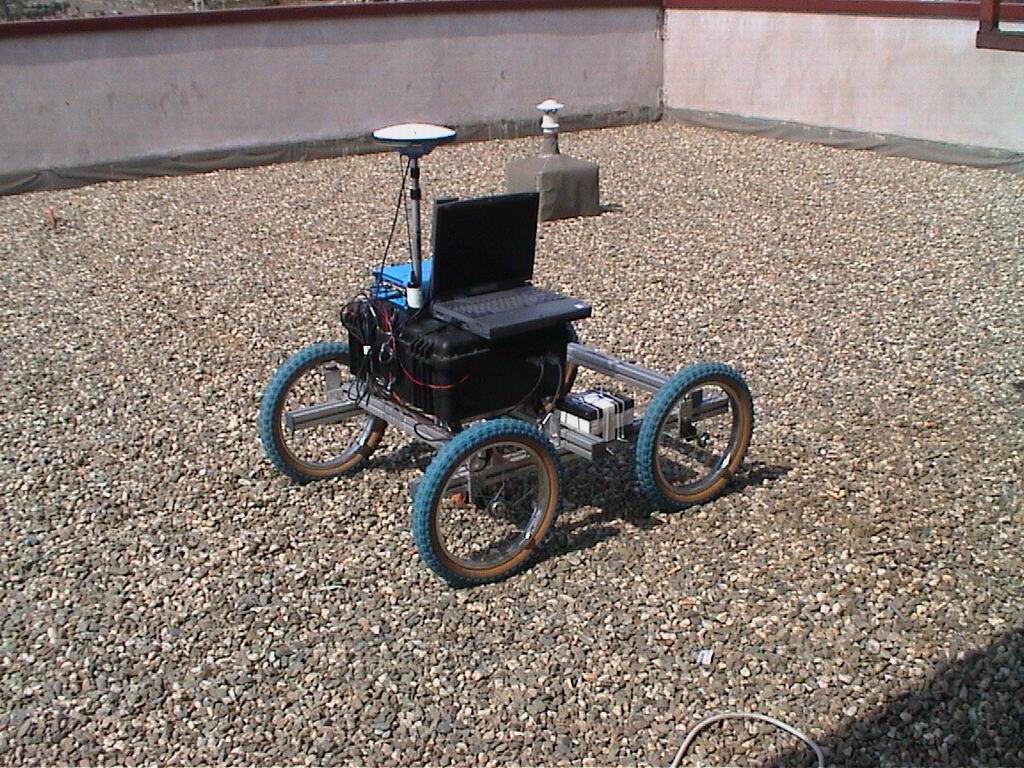
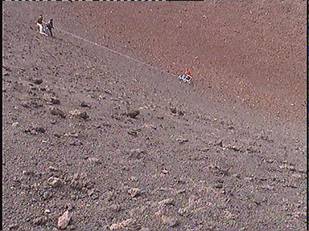
In order to measure volcanic terrain features a four wheel probe was built. This cart, shown in Fig. 2, was manually driven into quiescent craters, to simulate possible paths taken by a robot inside the craters. The probe carried the following instrumentation GPS, encoders in both wheels, a video camera, temperature, humidity and pressure sensors. A more detailed description is reported in the deliverable D2.b and in the articles [14] and [15].
Fig. 2. The Four wheel probe (a). Trial on volcanic site (b).
Using the measurements and following discussions with the end users the technical requirements for the ROBOVOLC robot concerning the selection of the platform were prepared (Deliverable D2.b). these requirements were then converted into the specification for the system (Deliverables D2.c, D3.1, D3.2).
The main criteria are:
- Modular components of system mass limit : 200Kg
- Maximum overall dimensions of modules: height- 0.8m, width- 1.2m, length- 1.7m
- Static Stability: 40°
- Maximum slope: 35° (minimum requirement is 30°)
- Maximum lateral obstacle height: 0.4m
- Speed: > 0.5m/s
- Maximum payload (scientific instruments and rocks collected): 30kg
- Travel time for a 24 hour mission: 1.5hours
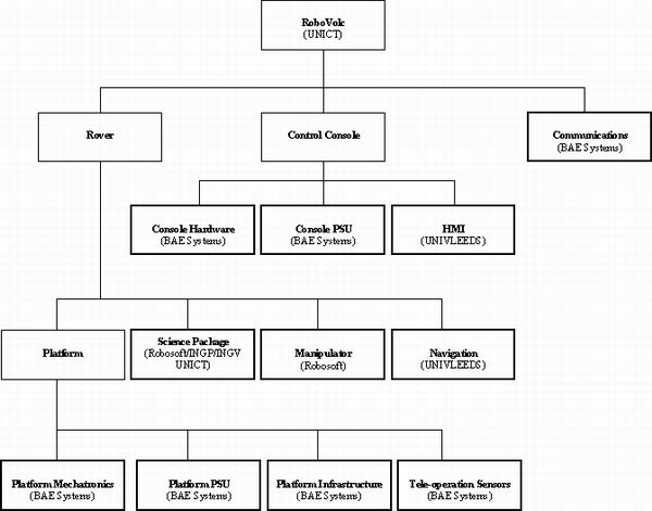
Fig. 3. Block diagram of the ROBOVOLC system.
Is important to stress that the preparation of such requirements and the consequent specifications arose from the fact that the ROBOVOLC consortium decided to design and build a system that could be extremely useful for volcanologists. As a consequence the final system is not a simple demonstrator made for the sake of academic robotic research.
The list of requirements was translated into a detailed list of specifications for the robot subsystems. In particular the subsystems considered are those described by the block diagram shown in Fig. 3.
Go Back to Menù
Selection of a locomotion architecture
The selection of the most appropriate locomotion technique for the ROBOVOLC system was carried out by evaluating the most promising techniques by comparing certain criteria e.g. reliability, rough terrain performance, suitability for purpose, etc. Eight techniques were evaluated; Tracked, Purely wheeled, Articulated and Cartesian walking robot, Frame walker, Hybrid “legs with wheels”, Flying (Fixed wing and rotary) and a Wheeled rover with High adaptive chassis. The initial selection was based on performance criteria derived from the user requirements, from this the most suitable concepts were under further review. The final contenders for the locomotion system were: Wheeled Rover with High Adaptive Chassis, Hybrid “leg with wheels” and Tracked Robot. These techniques have the potential to meet the requirements. Walking systems are, in fact, best suited for rough terrain but are too slow and difficult to control. Flying robots though extremely promising would have to contend with the additional hazards of strong winds and ash rain that occur near volcanic peaks. Flying robots need complicated control systems and the high payload requirement to carry all the scientific instruments would make the flying robot solution very expensive
Hybrid systems are very promising, since they should have both the advantages of wheeled and legged machines. Some investigation of hybrid systems was also carried out by the University of Catania with the WHEELEG system [16],[17],[18],[19],[20],[21]. Though some successful results were obtained, in some situations the drawbacks of wheeled systems (low traction) and of walking systems (unstable and difficult to control) were apparent.
The final selection of the most suitable concept was achieved by a qualitative assessment against key criteria. The criteria being that the solution be; able to achieve the user requirements and specifications; robust and reliable; easy to use and maintain; and have exploitation potential (cost effective).
The favoured vehicle concept was a six wheeled chassis with a large range active or passive suspension. It is expected that differential steering will be adequate for the specified requirements and improve robustness and reliability.
The selection of a hybrid system with adaptive chassis was based on the trial of two prototypes: the M6 and the L4 platform. The M6, shown in Fig. 4, has an articulated chassis capable of adapting to very rough terrain [22]. However not having a substantial central body, the payload of this system was low. The other solution, trialled with the L4 platform, (without prismatic joints connecting the rear and front wheel axes to the central body) allows higher payload capabilities (Fig. 5).
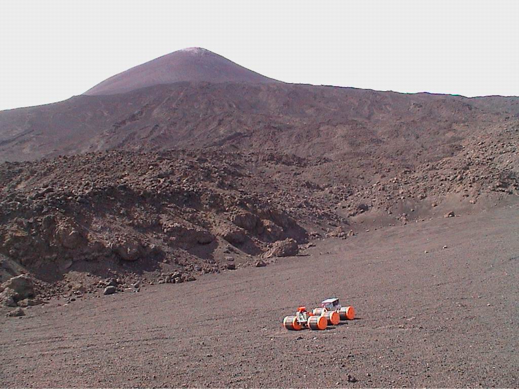
Fig. 4. The M6 Platform.
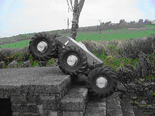
Fig. 5. The L4 Platform.
System description
In this section the main subsystems of the ROBOVOLC system will be described in some detail.
Control console
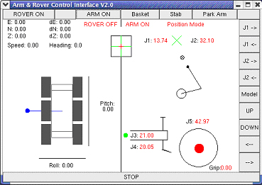
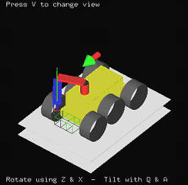
A user friendly man-machine interface was designed to allow the final users (the volcanologists) to drive the vehicle during the missions without specialist knowledge of the system. The control console allows users to remotely control the robot from a safe area. Two separate PCs make up the control console. The first one is specifically dedicated to drive the vehicle, while the second one is to control the scientific instruments.
The robot control console will be situated at a base station a safe distance from the volcano. The control console will operate software with which the robot will be commanded and feedback displayed. The control console's user interface is designed with the intention of providing the final users with the functionality to tele-operate the robot without specific knowledge of robotic systems, see Fig. 6 for user interface component designs. The control of the robot is accomplished by two joysticks and touch-screen/mouse input. Ergonomic considerations have been taken in account in the design of the HCI as a mission can be expected to be several hours in duration so employing graphics and customisable GUI (graphic user interface) is intended to reduce the eye-strain involved in understanding the various information displayed in the screens.
The science instruments will be controlled via a separate PC connected to the robot via LAN, using a http connection this will allow the science sensors to be controlled via a web-page interface.
Control of the low level functionality of the Rover (e.g. accessing localisation data, arm and Pan Tilt control) is implemented by RPC (remote procedure calls).
Fig. 6 User interface design.
Communication system
The telecommunications system is based on a redundancy system. This uses a standard high-power wireless LAN interface, for most of the data exchange at a high data rate (10Mbps) and a low speed radio modem (100kbps), for essential tele-operation e.g. when the robot is out of the line of sight of the base station.
Navigation system
Navigation can be divided into several stages. The position of the robot must be determined (localisation); its surroundings must be sensed and mapped; and finally decisions must be made as to how best to proceed. For most operations the decision-making process will be handled by a human operator (teleoperation), though a limited amount of autonomy is included for simple tasks such as repeating a previous path. This leaves the issue of sensing the robot’s position and environment.
Localisation system
The function of the localisation system is to determine the exact location of the robot both for navigation purposes and also to allow the volcanologists to reconstruct the terrain morphology. The main sensor adopted for localisation is a DGPS (Ashtec model Z-Xtreme) based on a Real Time Kinematic Differential GPS (RTK-DGPS) algorithm with an optimum position accuracy lower than one centimetre.
The precision of the DGPS can vary drastically. This can be caused by the loss of communication with the differential correction signal or to the interference of satellite signals reflected by nearby rocks. In these cases the accuracy of the DGPS can drop to several meters. However, a data fusion algorithm has been designed to optimise the accuracy of localisation data from the DGPS by merging it with input from other sensors. The sensors inputs include odometry data from the wheel encoders, rate of turn from a gyroscope, absolute orientation from a magnetic compass and the attitude of the robot measured by a two axis-inclinometer. The optimisation algorithm is based on an Extended Kalman Filter and the inputs are pre-filtered using a Fuzzy logic rule based procedure. When the DGPS signal is not reliable the algorithm automatically selects the most accurate sensor at the time. The shortcomings of each sensor are briefly described here (Details enclosed in Deliverable D4.fin and D7.fin). Encoder odometry is good for rectilinear trajectories, but is very bad during turning phases. In fact the skid-steering system does not allow a precise orientation measurement from the wheel positions during turns. On the other hand the gyroscope is an accurate sensor during turning phases, but it can only be relied on for brief time periods, the ever present drift in the sensor produces an accumulating orientation error. The compass is a good absolute heading sensor but is subject to the magnetic fields generated by the electrical brakes and motors, and is unlikely to be very accurate during motion.. Moreover volcanic rocks are often strongly magnetic, thus the compass orientation cannot be expected to be highly reliable. However, when the robot is stationary, the magnetic compass should provide a practically accurate heading estimate and is the only sensor available that can give an absolute orientation at the beginning of a mission or after a change of orientation.
The results of the data fusion algorithm have demonstrated a capability to maintain an accuracy of position lower than 3cm during periods of DGPS failure, even when the vehicle is continuously turning.
Mapping and obstacle avoidance
The Autonomous Navigation is based on Meystel’s hierarchical structure that models the cognitive processes employed in human navigation (e.g. when a person drives with a map). The rover will need to autonomously navigate in situations where the tele-operation is not available e.g., when the control signal is broken.
The autonomous navigation is implemented in a four-layer structure, shown in Fig. 7 (these layers are; long range planning, short range planning, instantaneous path and the motion control layer). These are described below.
The long range layer is concerned with the definition and management of the map based way-point path for the robot, this component informs the short range path layer what the current set of nearby way-points is.
This short range layer manages the navigation of the robot to the current waypoint objective (and signals to the long range layer when this is achieved). Also it communicates to the instantaneous path layer which direction the robot should head in and the preferred alternative direction if an obstacle is encountered.
This instantaneous path layer receives the heading instructions from the short range path layer and decides what path to take from the terrain data that it has. The terrain data is based on the scanning laser terrain model and tilt/attitude data from the localisation unit.
The motion control layer processes the low level motion control commands sent to it from the instantaneous path layer.
The four layer structure is shown diagrammatically in Fig. 7.
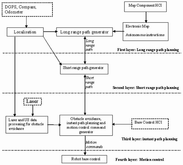
Fig. 7: Four layer autonomous navigation structure.
Platform
Platform mechatronics
As described earlier the platform is a six-wheeled system with an articulated chassis. The system has been equipped with semi-active joints connecting the front and rear axes to the body. These joints consist of two springs which have controllable stiffness. Tests over volcanic surfaces have revealed that this system outperforms some of the requirements coupled with the quality of mechanical robustness.
Platform Power supply Unit (PSU)
The chosen power supply solution employs lead acid batteries, however to extend mission duration a hybrid Internal Combustion (IC) engine has been designed and manufactured. The optimum mode of operation would be to use the IC generator in combination with the batteries, as a back up and recharge system. This arrangement would greatly extend mission duration and enhance the capability of the system.
Computer infrastructure
The infrastructure design is based on the utilisation of general purpose embedded computer boards, with a combination of COTS and bespoke software running on these platforms. The various tasks are distributed over three PC104 based computers located in the rover. The distribution of the Robovolc systems across three computers was chosen because it increases the reliability of the individual components. This is particularly true for rover motion control, with one PC dedicated to motion control, this reduces the likelihood that a failure in one of the other systems will result in the rover being unable to move.
The three PC’s and their tasks are allocated as follows :
- Rover PC (Linux OS): Rover motion, Low-Speed Communications, Traction control, Navigation control, Rover motion sensors
- Manipulator PC (Linux OS) : Manipulator motion,
- Science PC (Windows OS): Video inputs & switching, Localisation, Gas analyser, Geophysical sensors
The motion controllers selected are RoboSoft RMPC-555. These motor controllers are to be used for both Rover and Manipulator motion and are interfaced to the PCs through a CAN network.
Tele-operation sensors
The tele-operation of the robot on volcanic terrain is not a trivial task (see Fig. 8), since all the wheels should be observed and a good view of the frontal area is also fundamental. Consequently four fixed cameras have been installed on each side of the rover and a camera with zoom capability is mounted on the pan/tilt turret. Also during tele-operation in active volcanic areas the use of an infrared camera will help avoid hazardous hot regions. Information from the inclinometers is also available to the operator to maintain the stability of the rover.
Go Back to Menù
Science package
The Science package can be decomposed into three main subsystems: the Manipulator, the Pan-tilt turret and the gas sampling system.(Details described in D4.fin).
The manipulator
A 5 degree of freedom SCARA manipulator has been specifically designed for the Robovolc system. Fig. 9 shows the manipulator mounted on the rover. The manipulator will be adopted to collect samples of rocks, to drop and pick up instruments at specific locations and to collect gas samples in the proximity of fumaroles. It's actuators are DC motors with encoders for position feedback. A three-finger gripper, shown in Fig. 10, has been designed with force sensors to pick up rocks with a maximum diameter of 15 cm.
Pan/Tilt turret
On the Pan/tilt turret (Also visible in Fig. 9)the following sensors are installed: a digital video-camera recorder, a high resolution still-image camera, a video-camera, an infrared camera and a Doppler radar for gas speed measurement. The user can orient the turret and can tele-operate all the installed sensors.
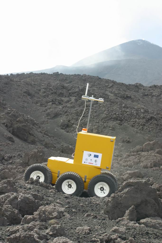
Fig. 8: Test of the platform in rough terrain
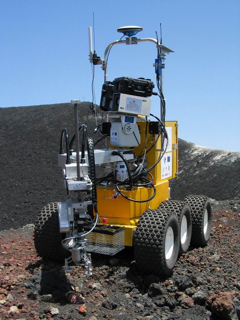
Fig. 9: The complete final system.
Fig. 10. Close up of the gripper.
Gas sampling system
Gas sampling is the most important measurement to be carried out by the robot. The analysis of the gas ejected from volcanic vents is one of the main indicators of volcanic activity. The main problems with this operation are: sampling gas that reach temperatures above 600°C ; the presence of extremely corrosive acid components; and the avoidance of gas mixing with the surrounding atmosphere resulting in corrupted samples.
To perform precise sampling a new system has been specifically designed for the Robovolc project. The system is composed of:
A probe for sampling the gas: This probe is comprises a small diameter titanium tube 1.5 m long, with a thermocouple on its tip and an Oxygen sensor. These two sensors will be used to assess the quality of the samples to be taken. The probe is also equipped with a thermal control system with the purpose cooling the gas temperature below 200°C to allow the gas to flow through flexible Teflon pipes. At the same time the temperature must also be maintained over 120°C to avoid water condensation that can corrupt the measurements.
A gas collection system: this system is made of teflon pipes, a set of valves, pumps, dryer and condensers to initially clean the circuit and to collect the gas samples in two bottles, when the samples are assesses to be reliable. A CO2 sensor and several termocouples are also included in the circuit.
A set of gas sampling bottles: at the top of these bottles a high degree of vacuum is maintained, while the bottom of each bottle is filled with NaOH. When the valves in the bottom of the bottle are opened the gas sample will enter the bottles.
A tele-operated control system will allow the sequence of operations for sampling and measurement to be controlled.
Go Back to Menù
References
[1] S. Williams, F. Montaigne, "Surviving Galeras", Houghton Mifflin Co; 2001.
[2] E. Zebrowski, "The Last Days of St. Pierre: The Volcanic Disaster that Claimed 30,000 Lives", Rutgers University Press, 2002.
[3] S. Alwyn, "La Catastrophe: The Eruption of Mount Pelee, the Worst Volcanic Disaster of the 20th Century", Oxford University Press, 2002.
[4] G. Muscato, G. Nunnari, S. Guccione, "Robots for Volcano Exploration: A New Perspective", World Automation Congress (WAC2000), Eight International Symposium on Robotics with Applications, Maui (Hawaii, USA), 11-16 June 2000.
[5] S. Guccione, G.Muscato, G.Nunnari, G.S. Virk, A.K.M. Azad, A. Semerano, M. Ghrissi, T.White, C. Glazebrook, "Robots for Volcanos: The State of the Art", Proceedings of the 3rd International Conference on Climbing and Walking Robots (CLAWAR 2000), pp.777-788, Madrid (Spain), 2-4 October 2000.
[6] Dante project WEB site: http://img.arc.nasa.gov/dante/dante.html
[7] J.E. Bares, D.S. Wettergreen, "Dante II: Technical Description, Results and Lessons Learned", The International Journal of Robotics Research, pp. 621-649, July 1999.
[8] Wettergreen, D.; Pangels, H.; Bares, J. ,"Behaviour based gait execution for the DANTE II walking robot", Proceedings. 1995 IEEE/RSJ International Conference on Intelligent Robots and Systems 95.'Human Robot Interaction and Cooperative Robots', Volume: 3 , 1995 , Page(s): 274 -279.
[9] Apostolopoulos, D.; Bares, J., "Locomotion configuration of a robust rappelling robot", , Proceedings. 1995 IEEE/RSJ International Conference on Intelligent Robots and Systems 95. 'Human Robot Interaction and Cooperative Robots' Volume: 3 , 1995 , Page(s): 280 - 284.
[10] Krishna, M.; Bares, J.; Mutschler, E. "Tethering system design for Dante II", Proceedings., 1997 IEEE International Conference on Robotics and Automation, 1997, Volume: 2 , 1997 , Page(s): 1100 - 1105.
[11] Marsokhod project WEB site: http://web99.arc.nasa.gov/~mars/marsokhod/
[12] A. Kemurdjian, V, Gromov, V. Mishkinyuk, V. Kucherenko, P. sologub, "Small Marsokhod Configuration", Proceedings of the IEEE International Conference on Robotics and Automation, Nice, France 1992.
[13] YAMAHA helicopter news: http://www.yamaha-motor.co.jp/news/2000-04-24/sky-e.html
[14] A.K.M. Azad, G.S. Virk and M. Qi, G. Muscato, S. Guccione, G. Nunnari, T. White, C. Glazebrook, A. Semerano, M. Ghrissi, P. Briole, C. Faucher, M. Coltelli, G. Puglisi, R. Cioni and M. Pompilio, "ROBOVOLC: Remote Inspection for Volcanoes", Workshop on Autonomous artificial systems exploring hostile environments, International NAISO Congress on Information Science Innovations (ISI'2001), Dubai, March 18th 2001.
[15] G. Muscato, S. Guccione, N. Savalli, M. Coltelli, G. Puglisi, P. Briole, C. Faucher, G.S. Virk, A. Azad, A. Semerano, V. Duporque, T. White, G.S. Rees, "Further progress in the development of the ROBOVOLC system", 4th International Conference on Climbing and Walking Robots CLAWAR 2001, pp. 997-1004 Karlsruhe (Germany), 24-26 September 2001.
[16] G. Lami, S. Guccione, G. Muscato, "Control Strategies and Architectures for the Robot WHEELEG", Proceedings of the 3rd International Conference on Climbing and Walking Robots (CLAWAR 2000), pp.327-338, Madrid (Spain), 2-4 October 2000.
[17] S. Guccione, G. Muscato, "Experimental outdoor and laboratory tests with the hybrid robot WHEELEG", Proceedings of the 3rd International Conference on Field and Service Robotics, Helsinki (Finland) June 11-13, 2001
[18] G. Muscato and G. Nunnari, “Leg or Wheels ? WHEELEG a hybrid solution”, CLAWAR 99 International conference on climbing and Walking Robots, Portsmouth, U.K. , 14-15 September 1999.
[19] M. Lacagnina, G. Muscato, R. Sinatra, "Kinematics of a hybrid robot Wheeleg", 5th IEEE International Conference on Intelligent Engineering Systems 2001, Helsinki (Finland), 16-18 Sep 2001.
[20] S. Guccione, G. Muscato, "Test of the hybrid robot WHEELEG on a Volcanic Environment", Proceedings of the 2001 IEEE/ASME International Conference on Advanced Intelligent Mechatronics, Como, Italy July 2001, p.3.
[21] S. Guccione, G. Muscato, "Control Strategies Computing architectures and Experimental Results of the Hybrid Robot Wheeleg", IEEE Robotics and Automation Magazine, , (IEEE Piscataway, U.S.A.), December 2003.
[22] M. Lacagnina, S. Guccione,G. Muscato, R. Sinatra, "Modelling and Simulation of Multibody Mobile Robot for Volcanic Environment Explorations", Proceedings of the IEEE/RSJ International Conference on Intelligent Robots and Systems, IROS 2002, Lausanne Switzerland, Sep.30-Oct.4 2002.
Go Back to Menù
|