|
|
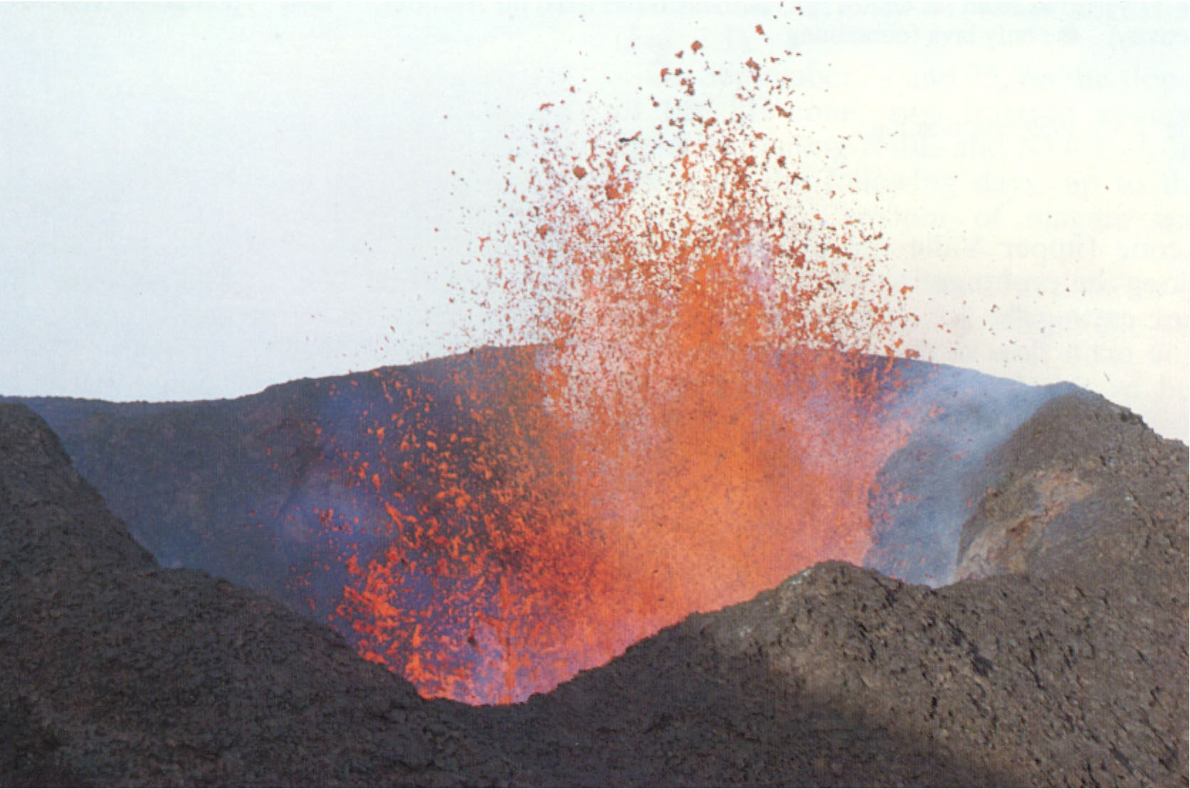
Fig.1: Paroxismal phase of Etna. |
Fig.2: Example of terrain around Mt. Etna. |
PAPER PRESENTED AT CLAWAR 2000 CONFERENCE
MADRID OCTOBER 2000
S. Guccione, G. Muscato, G. Nunnari
Dipartimento Elettrico Elettronico e Sistemistico, Universitŕ di Catania, Italy
e-mail: gmuscato@dees.unict.it
G.S. Virk, A.K.M. Azad
Department of Electrical and Electronic Engineering, University of
Portsmouth, UK
A.Semerano, M. Ghrissi
Robosoft, Biarritz, France
T. White, C. Glazebrook
Portsmouth Technology Consultants Ltd, Portsmouth, UK.
ABSTRACT
This paper discusses the state-of-the-art in the area of mobile robots for
outdoor applications with particular attention to extremely rough environments
such as those found in volcanic and planetary exploration applications. The
paper looks at the area of locomotion, manipulations, sensors, control and
navigational methods that are available so that the most appropriate can be
identified. The intention is therefore to present a survey paper rather than new
research but the applicability of the current technology to such environments
will be studied and shortcomings reported. This study is part of an EC project
to develop a mobile robot that can inspect active volcano vents. Mt. Etna in
Italy will be used as the primary test bed but trials at Stromboli and
Montserrat (UK Antilles) are also planned.
Such reasons together with recent advances in robotics have inspired a new EC project named ROBOVOLC with the aim of building a robot for volcanic exploration whose activities started on March 2000. The partnerships includes two Universities and two industrial organisations stated above and two research organisations who provide the expertise in volcanology: Istituto Internazionale di Vulcanologia CNR, Italy and Institute de Physique du Globe de Paris, France. A more detailed description of the project with the latest updates can be found in the project WEB pages: http://www.robovolc.dees.unict.it.
A major aim for this project will be that of minimising the risk for volcanologists and technicians who are involved in work close to volcanic vents during eruptive phenomena. It should be noted that observations of, and measurement of the variables relating to volcanic activity are of greatest interest during paroxismal phases of eruptions, which unfortunately are also the time of greatest risk for humans.
Volcanologists have identified that a robot for volcano exploration should be able to do many operations, but the most important are that it must be able to:
|
|
|
Fig.1: Paroxismal phase of Etna. |
Fig.2: Example of terrain around Mt. Etna. |
The sites to be examined are lava flows, ash and spatter cones and large fractures on the ground; in general they are very rough and disconnected surfaces close to or inside volcanic craters. The ground often has a steep gradient and its surface is unstable due to rolling rocks or sliding materials, so the robot is likely to need a sophisticated leg-wheel assembly to move safely and surely. Sometimes the place being investigated will be previously unexplored so a video link between the rover robot and the operator is essential. A ranging system (i.e. laser ranging) will be useful for both driving and measurement purposes. Finally an efficient data link will be required to drive the rover and to download the collected data.
In order to achieve such results, new algorithms and software for autonomous and/or semi-autonomous navigation of a robot in unstructured environments will be developed. For autonomous navigation, we intend that the robot should be capable of reaching a given position in the volcanic area autonomously and automatically perform the tasks required to perform the measurements. In the case of very difficult or dangerous situations (e.g. proximity to lava flows or fissures), the robot will be tele-operated and able to act in a semi-autonomous way. In this case, by using a specifically designed user interface, an operator will be able to drive the robot effectively from a safe place. For semi-autonomous use, we intend that the robot will have the capability of deciding autonomously some sub-tasks, e.g. the control of the position of individual wheels or legs, measurement operations, etc.
Data collected by the robot will be used primarily to enhance knowledge of the volcanic process and to produce computer simulation software of the volcanic phenomena. The capability to furnish updated information during eruptions will be used as input data for the simulation software to adjust the trend forecasts for long-lived volcanic phenomena such as lava flow eruptions.
The first step of the ROBOVOLC project consisted in the analysis of the state of the art in mobile robots for rough terrain. If the attention is concentrated on recent projects with the specific objective of volcanic exploration only a few systems have been developed. However it should be observed that, following also the successful results of the Sojourner in the exploration of Mars, many new robots have been designed for planetary exploration. In many cases such robots have been tested on volcanic surfaces, due to the fact that there are strong similarities with planetary terrain.
In the following subsections three big projects concerning a legged, a
wheeled and a flying robot adopted in volcanic exploration are briefly
reviewed, then in the next section more general considerations on the state of
the art in the various technologies that are needed will be presented.
Dante II is an multi-legged frame walking robot that was designed by NASA and Carnegie Mellon University to investigate live volcanoes and help test robotic technology for NASA [1-4]. The robot is a framewalker with eight pantographic legs arranged in two groups of four, on inner and outer frames. Dante II is connected by a tension-controlled tether to maintain stability and to allow rappelling on steep slopes [5].
In 1994 Dante II was adopted to explore the Mount Spurr volcano in
Alaska. For more than five days the robot explored alone in the volcano
crater using a combination of supervised autonomous control and teleoperated
control. The legged robot travelled one-quarter of its 165-m descent
autonomously, relying only on onboard sensors and computers to plan and
execute its motion. The terrain was very rough including crossing 1-m
boulders on ash-covered slopes, navigating areas of deep snow, ditches and
rubble. The robot was adopted to measure the gas composition of several
large fumarole vents.
[2]. However while climbing out of the crater, Dante II lost
stability and fell on its side thus ending its mission. The Dante II/Mt.
Spurr expedition was considered a success because of the amount of data and
experience that was accumulated. Dante II was successful in retrieving data
from a very harsh environment such as might be the case in missions to other
planets. This also gave NASA the opportunity to determine what improvements
are needed for future robotic missions.
The Marsokhod rover is an all terrain vehicle developed by the Mobile Vehicle Engineering Institute (VNIITransmash) in Russia for planetary exploration [7]. The chassis (100cm wide, 150cm long, 35kg unloaded mass) consists of three pairs of independently driven titanium wheels joined together by a three degree of freedom passively articulated frame. This design enables the rover to conform passively to very rugged terrain. The amplifiers, motors and batteries are mounted inside the wheels to produce a very low centre-of-gravity. The robot can travel at speeds up to 12 cm/sec and can traverse obstacles up to 30 cm high and slopes of up to 45°. The autonomy of operation with batteries is about 6 hours.
The Marsokhod robot even if designed for Mars explorations has been
extensively tested in volcanic surfaces such as in Kamchatka, Russia in
1993, in the Amboy crater test in California in 1994 and the Kilauea Volcano
test in Hawaii in 1995. Kilauea Volcano was selected primarily for its great
diversity of geologic features similar to those expected on Mars and the
Moon [6].
There is a huge number of examples of wheeled mobile robots developed in the last decades. However in this section only machines specifically designed for rough environments will be briefly classified and described. Most of these machines have six legs in order to obtain more static and dynamic stability.
A common feature of many wheeled robots is the fact that they possess a passively articulated frame that allows to easily adapt them to the surface irregularities. To these category belongs the robots NOMAD, MARSOKHOD, SHRIMP, SOJOURNER, ROCKY 7, FIDO and ATHENA.
NOMAD was developed by JPL to demonstrate and evaluate robotic systems capable of long distance, long duration mission [9]. This four-wheeled robot features a transforming chassis that can expand or compact by driving two pairs of four-bar linkages with two electric motors, one on each side of the robot. Moreover Nomad has two floating side frames that supports and deploys two wheels. Individual propulsion drive units reside inside each wheel. In the past 3 years, Nomad has completed three very successful missions, one in the Atacama desert and two in Antarctica. The latest of these has led to the first meteorite discovery by a robot [9-12].
SHRIMP is a wheeled rover developed by EPFL Lusanne (Switzerland) for planetary explorations [13]. It is a six-wheeled rover, with one wheel in the front mounted on an articulated fork, one wheel in the rear directly connected to the body of the rover and two wheels mounted on two lateral bogies. The only actuators are the motorised wheels allowing to adapt purely passively to the terrain. The rover is able to overcome steps that are twice its wheel diameter and can climb regular stairs. Moreover, Shrimp shows excellent off-road capabilities of overcoming rocks and obstacles even with a frontal inclination of 40°.
Sojourner, Rocky7, Fido and Athena robots are four similar robotic roving vehicles with six- wheeled chassis and a rocker-bogie system. Sojourner, developed by JPL, was the first robotic autonomous vehicle sent to Mars in July 1997 [14]. Rocky 7 is an improvement of the Sojourner designed to expand its capabilities while increasing the range of operations [15-18]. Fido is a larger version equipped with a 5 degrees of freedom instrument arm on which three science instruments are mounted at the end effector location [19].
Other important vehicles to be considered are the MUSES (four-wheeled
nanorover developed by NASA laboratory and JPL for the exploration of
asteroid surfaces [20])
and commercial vehicles such as the HOBO of Kentree in Ireland [21].
Unmanned Aerial Vehicle (UAV) is a research field with a great interest both for commercial and for military applications. There are many different kinds of vehicles designed and many research groups are working to build completely autonomous vehicles able to reach a given location without teleoperation. A classification can be done between Helicopters, Airships and Aeroplanes. Projects involving helicopter vehicles includes the CMU Helicopter [22], the ASRT [23], the CYPHER by Sikorsky Aircraft [24], the CAMCOPTER [25], the AROD [26]. Airship research projects include the AURORA adopting an Airspeed Airship [27] and SASS LITE of Bosch Aerospace [28]. Projects on small autonomous aeroplanes include the Aerosonde [29], the Global Hawk [30], the MUAV [31], the VINDICATOR [32], and many other not mentioned here for space reasons.
However from the point of view of the ROBOVOLC project it should be
taken into considerations that many of these UAV do not work suitably at
high altitude (Mt Etna height is 3300m), are sensible to strong wind
conditions, have no resistance to the impact of even small rocks and
sometimes require well-trained operators.
Hybrid robots are machines that integrate both wheels and legs in order
to obtain a compromise between the capabilities of totally legged machines
(adaptability to very rough terrain) and totally wheeled machines (speed,
autonomy, stability). Among the examples of such a kind of robots there is
the CHARIOT [33](with
two wheels and four legs, the big drive wheels are located on each side of
the body while there are two legs on each end), the WHEELEG [34]
with two front legs and two rear wheels and the WORKPARTNER with four
wheels each one mounted at the end of one leg [35].
This section presents brief summary on the legged and hopping machines that have been produced over recent years. These can be group in many ways such as application, type of actuation or number of legs. For convenience we describe the machines by leg number and start with one-legged machines as several such machines have been developed. Clearly these can only move by hopping from one place to the other. The first such machine was developed by Marc Raibert at Massachussetts Institute of Technology. Several one-legged hoppers have been subsequently developed at MIT and elsewhere, e.g. MacGill.
Biped research has received considerable interest and Japan has a major R&D programme where the aim is to produce a human-friendly system that can interact with humans in their everyday environments. The most advanced of these is the Honda biped P3 system which can demonstrate a number of complex operations such as going up and down stairs, turning, etc.[36].
Only one three-legged machine has been developed to the authors knowledge. This is the Robinspec magnetic climbing machine developed at the University of Catania [37]. The machine is able to work on ferrous surfaces for remote inspection.
There are numerous examples of four-legged systems and Germany has a major R&D programme in this area. The most advanced four-legged system that has been developed to date is probably Sony’s pet robot, AIBO [38]. Sony has invested major effort in developing the AIBO robot through an extensive network of universities across the world. The universities have been developing different aspects of the system, ranging from sensing, mechanical design, actuation, autonomy, etc., and the system developed has now been commercialised with considerable success. Over 40,000 units have been sold for $2,500 each and there is now an annual soccer playing competition where each team comprises four AIBO robots that have to play a game of football against another team of four AIBO robots [39].
A number of six-legged robots mainly developed using ideas from nature such as insects and has incorporated a number of sensors and neural control methodologies. These include Ioan (ULB, Belgium), Ambler and Daedalus (Carnegie Mellon), Rest (CSIC-IAI, Sain), Mecant (Helsinki University of Technology, Finland), Forest Walking Machine (Plustech, Finland) and Hercules (Robosoft and LRP, France).
Only one seven legged machine has been identified - this is the Walking Beam machine developed by Lockheed Martin, USA for NASA.
Several eight-legged machines have been developed based again on
biological thinking, such as spiders and crabs. The main machines
identified are Robug III and Robug IV developed by University of
Portsmouth and Portech respectively. Both are pneumatically powered and
can walk and climb. Robug IV is an extension of the Robug III thinking to
a smaller, more compact format with much more emphasis on modularity. The
overall design has been much more refined and more advanced than the
thinking adopted in Robug III. Another eight-legged pipe climbing robot
has been developed by Professor Lawitzky of Siemens AG, Munich. The eight
legs allow the machine to support itself and climb up by pushing against
the wall.
At present, the consortium is assessing whether an off-the-shelf manipulator can be used or if a custom design is more adequate for achieving the required functionality.
Following the formulation of the volcanologists’ requirements, it is apparent that the manipulators needed must satisfy the following specifications:
|
|
Fig. 3: TSR202 tracked. |
Fig. 4: RM32 medium-size wheleed. |
If the commercially available mobile manipulators are able to meet ROBOVOLC’s requirements, tele-operation is felt to be the best way of carrying out the tasks. A survey on the off-the-shelf tele-operational manipulator systems has been carried out. This has revealed the following:
As already stated, the design of the ROBOVOLC platform will need to address a broad range of problems in order to culminate in a reliable, robust and effective "tool" for the observation and measurement of the required volcanic phenomena. The primary requirement is clearly the ability to traverse the wide variety of rough terrain. It is anticipated that the final design will be a trade off between ability to negotiate terrain, travelling speed and the energy consumed.
Preliminary investigations have indicated that a hybrid design using legs and wheels could be suitable but may be difficult to control. A wheeled machine with good suspension capability for each wheel or some form of "walking" capability may be a good compromise. The actual platform design has not been finalised at this time, but several concepts are being analysed for suitability.
The mechanical design philosophy for the ROBOVOLC project is being developed from studying the user requirements and the current state of the art in robotics. Experience from previous robotic deployments into volcanic craters and for planetary exploration such as Dante II [2] and the Marsokhod robot [7], have been used in the thinking of the consortium. High power-to-weight ratios, over designing, maximising modularity and system redundancy have been the most important issues raised by the initial studies. We expect that the robot will encounter situations that were not exactly predicted. Past experience has also shown that integration of the robot sub-system modules can cause major stresses to the components. However high power/weight ratio and over design in conjunction with other elements will ensure that the robot can withstand and overcome these situations successfully and remain mechanically intact. This does not negate the proper design procedures involving simulation and model testing.
The concept of mechanical modularity will be an important feature in the design for several reasons. The ability to modify the robot to suit different mission profiles will provide efficient use of the platform. The capacity to reconfigure/remove unwanted modules will allow greater flexibility, for example increasing the rock sample carrying capacity or more fuel to extend the duration of the mission. It would also be possible to make available different modules to suit different terrain structures thus allowing the robot to extend its capabilities without unduly increasing the overall size and weight.
The issue of system redundancy will be addressed to ensure that the
mechanical system is capable of recovering from failures without the total
loss of the robot. The obvious hazards of the environment include the
potential of damage from flying debris and other threats. As well as
mechanical robustness and redundancy will mitigate these threats to give a
reasonable level of confidence that the robot will survive most situations
presented.
In any case the real time 3D reconstruction could be considered using
these kind of sensors.
Navigational tasks for a mobile robot are clearly important as this involves addressing the problems of localisation, direction to move to reach the target, determining the environmental situation and to finding the optimum path to follow [40]. Generally speaking, there are two main methods for determining the robot’s position, namely relative and absolute positioning. Relative positioning involves odometry that uses encoders to measure wheel rotation, steering information and inertial navigation via gyroscopes and accelerometers. Absolute positioning involves using beacons (active or passive) and global positioning systems (GPS), natural and artificial landmark recognition, natural landmark recognition and model matching methods.
[41].
For relative positioning systems, sensor data can be scaled by a known factor to obtain the actual position of the machine. This method is an important part of a mobile robot navigation system and can provide good short-term accurate predictions through high sampling rates with minimum cost. However, the fundamental idea of relative positioning for longer time horizons leads to poor accuracy because of accumulation of the error [42]. Active beacon-based methods are the most common as they can provide accurate positioning information with minimal processing (see for example [43]). Active beacon systems have been proven in practice, and there are several commercial systems available that use lasers, infrared and ultrasonic transducers and which can derive the robot’s location via triangulation of the received beacon signals. For more technical information of these system refer to [44] for localisation using laser and passive reflectors and [45] for transponders system.
Global positioning systems can also be used for finding the absolute 3D location using trilateration techniques based on time of flight for uniquely coded spread-spectrum radio signals transmitted by satellites. The method is conceptually simple but many factors need to be considered during the system design phase. These include time synchronisation between individual satellites and the GPS receivers, precise real-time location of the satellites’ positions, accurate measurement of signal propagation times and ensuring sufficient signal-to-noise ratios for reliable operation in the presence of interference and possible jamming.
Also, due to security reasons, small errors in timing and satellite positions have been deliberately introduced for commercial applications of GPS and this leads to positional accuracies of around 2 to 3 meters. Differential GPS can achieve far better and can have an accuracy of 1mm to 1cm range [4][53].
Landmarks (natural or artificial) are distinct features that a robot can
recognise for the purposes of localisation. Natural landmarks are clearly
objects or features that normally exist in the environment whereas
artificial ones are special markers placed at known locations in the
environment with the sole purpose to enabling robot navigation. Different
kinds of artificial landmarks include patterns or marks, retro-reflective
barcodes and beacons. Detection is much easier with artificial landmarks,
which are designed for optimal contrast [47],
[48]
and many are based on computer vision. Other methods that can be used
include line navigation [49] and map-based methods (where map is either
pre-stored or created in an on-line manner) [50],
[51].
ACKNOWLEDGEMENTS
This work was supported by the EC Project ROBOVOLC IST–1999 10762.
[2] J.E. Bares, D.S. Wettergreen, "Dante II: Technical Description, Results and Lessons Learned", The International Journal of Robotics Research, pp. 621-649, July 1999.
[3] Wettergreen, D.; Pangels, H.; Bares, J. ,"Behaviour based gait execution for the DANTE II walking robot", Proceedings. 1995 IEEE/RSJ International Conference on Intelligent Robots and Systems 95.'Human Robot Interaction and Cooperative Robots', Volume: 3 , 1995 , Page(s): 274 –279.
[4] Apostolopoulos, D.; Bares, J., "Locomotion configuration of a robust rappelling robot", , Proceedings. 1995 IEEE/RSJ International Conference on Intelligent Robots and Systems 95. 'Human Robot Interaction and Cooperative Robots' Volume: 3 , 1995 , Page(s): 280 –284.
[5] Krishna, M.; Bares, J.; Mutschler, E. "Tethering system design for Dante II", Proceedings., 1997 IEEE International Conference on Robotics and Automation, 1997, Volume: 2 , 1997 , Page(s): 1100 –1105.
[6] http://web99.arc.nasa.gov/~mars/marsokhod/
[7] A. Kemurdjian, V, Gromov, V. Mishkinyuk, V. Kucherenko, P. sologub, "Small Marsokhod Configuration", Proceedings of the IEEE International Conference on Robotics and Automation, Nice, France 1992.
[8] http://www.yamaha-motor.co.jp/news/2000-04-24/sky-e.html
[9] http://www.frc.ri.cmu.edu/projects/meteorobot2000/
[10] S. Moorehead, R. Simmons, D. Apostolopoulos, and W.L. Whittaker, "Autonomous Navigation Field Results of a Planetary Analog Robot in Antarctica", International Symposium on Artificial Intelligence, Robotics and Automation in Space, June, 1999.
[11] Bapna, D.; Rollins, E.; Murphy, J.; Maimone, E.; Whittaker, W. Wettergreen, D., "The Atacama Desert Trek: outcomes ", Proceedings. 1998 IEEE International Conference on Robotics and Automation, Volume: 1 , 1998 , Page(s): 597 –604.
[12] Rollins, E.; Luntz, J.; Foessel, A.; Shamah, B.; Whittaker, W., "Nomad: a demonstration of the transforming chassis", Proceedings. 1998 IEEE International Conference on Robotics and Automation, 1998 Volume: 1 , 1998 , Page(s): 611 –617.
[13] T. Estier, Y. Crausaz, B. Merminod, M. Lauria, R. Piguet, R. Siegwart, "An innovative Space Rover with extended climbing abilities", Proceedings of Space and Robotics 2000, Albuquerque USA, February 27-March 2, 2000.
[14] Mishkin, A.H.; Morrison, J.C.; Nguyen, T.T.; Stone, H.W.; Cooper, B.K.; Wilcox, B.H, "Experiences with operations and autonomy of the Mars Pathfinder Microrover", 1998 IEEE Aerospace Conference, Volume: 2 , 1998 , Page(s): 337 –351.
[15] Hayati, S.; Volpe, R.; Backes, P.; Balaram, J.; Welch, R.; Ivlev, R.; Tharp, G.; Peters, S.; Ohm, T.; Petras, R.; Laubach, S., "The Rocky 7 rover: a Mars sciencecraft prototype", Proceedings 1997 IEEE International Conference on Robotics and Automation, Vol. 3 , 1997 , Page(s): 2458 –2464.
[16] Tarokh, M.; McDermott, G.; Hayati, S.; Hung, J., "Kinematic modeling of a high mobility Mars rover", Proceedings. 1999 IEEE International Conference on Robotics and Automation, Vol. 2 , 1999 , Page(s): 992 –998.
[17] Volpe, R.; Balaram, J.; Ohm, T.; Ivlev, R., "The Rocky 7 Mars rover prototype", Proceedings of the 1996 lEEE/RSJ International Conference on Intelligent Robots and Systems '96, IROS 96, Vol. 3 , 1996 , Page(s): 1558 –1564.
[19] http://eis.jpl.nasa.gov/rmet/
[20] http://robotics.jpl.nasa.gov/tasks/nrover/homepage.html
[22] http://www.cs.cmu.edu/afs/cs/project/chopper/www/index.html
[25] http://www.schiebel.com/industries/product.htm
[26] http://www.nosc.mil/robots/air/arod/arod.html
[28] http://www.boschaero.com/ship_mil.htm
[29] http://www.aerosonde.com/
[30] http://www.tdyryan.com/04_Programs/Global%20Hawk/Global%20Hawk.html
[31] http://www.i-a-i.com/iai/templates/temp_p4.asp?content_id=290
[32] http://www.nomadfleet.com/vindicator_uav.html
[33] http://www.robotics.is.tohoku.ac.jp/lab/intro.html
[34] http://www.scg.dees.unict.it/giovanni/WHEELEG.HTM
[35] http://www.automation.hut.fi/IMSRI/workpartner/
[36] http://www.honda.ac.jp/english/technology/robot/
[37] http://www.scg.dees.unict.it/giovanni/ROBIN.HTM
[38] http://www.world.sony.com/aibo
[39] http://www.robocup.org/.
[40] Leonard, J. and Durrant-Whyte, H. F. (1991). Mobile Robot Localization by Tracking Geometric Beacons, IEEE Transactions on Robotics and Automation, Vol.7, No.3, pp.376-382.
[42] Cox, I. J., (1991). Blanche - An Experiment in Guidence and Navigation of an Autonomous Mobile Robot, IEEE Transactions Robotics and Automation, Vol.7, No.3, pp. 193-204.
[43] Maddox, J., (1994). Smart Navigation Sensors for Automatic Guided Vehicles, Sensors, April, pp.48-50.
[45] http://www.frog.nl/
[46] Hurn, J., (1993). GPS, A Guide to the Next Utility, No. 16778, Trimble Navigation, Synnyvale, CA, November.
[47] Atiya, S. and Hager, G. (1993). Real-time Vision-based Robot Locomotion, IEEE Transactions on Robotics and Automation, Vol. 9, No.6, pp. 785-800.
[48] Feng, L., Fainman, Y. and Koren , Y. (1992). Estimate of Absolute Position of Mobile Systems by Opto-electronic Processor, IEEE Transactions on Man, Machine and Cybernetics, Vol.22, No.5, pp.954-963.
[49] Talluri, R. and Aggarwal, J., (1993). Position Estimation Techniques for an Autonomous Mobile robot - A Review. Handbook of Pattern Recognition and Computer Vision, World Scientific: Singapore, Chapter 4.4, pp.769-801.
[50] Buchberger, M., Jörg, K. and Puttkanmer, E. (1993). Laserradar and Sonar Based World Modeling and Motion Control for Fast Obstacle Avoidance of the Autonomous Mobile Robot MOBOT-IV, Proceedings of IEEE International Conference on Robotics and Automation Atlanta, GA, May 10-15, pp.534-540.
[51] Jörg, K. W. (1995). World Modelling for an Autonomous Mobile Robot Using Heterogeneous Sensor Information, Robotics and Autonomous Systems, Vol.14, pp. 159-170.
[52] Oriolo, G. Ulivi, G. And Vendittelli, M. (1998). Real-time Map Building and Navigation for Autonomous Robots in Unknown Environments, IEEE Transactions on Systems, Man and Cybernetics, Part B, Vol.28, No.3.
[53]. http://www.colorado.Edu/geography/gcraft/notes/gps/gps_f.html