|
|
| Attendees | |
| Outline | |
| Picture Gallery | |
| Video Gallery |
Attendees
- INGV : Gaetano Giudice and Salvatore Giammanco.
Outline
During the mission of 11 April 2003 at Vulcano Island the materials and sensors to be used for the geochemical system on RoboVolc have been tested.
The titanium probe designed for the project has been used. The probe is 1.5 m long, with internal diameter of 4 mm. It is heated externally with a heating element of total power of about 100 W, so as to keep the fumarolic gases inside the probe at a temperature higher than 100 °C. This in order to avoid both the condensation of steam and the chemical and isotopic fractionation of gases.
The tests to verify the correct operation of the system have been carried out at the Spiaggia di Levante beach on Vulcano, near the Mud Pool. The sampling system for the fumarolic gases was made of an inverted pyrex funnel placed into the ground to a depth of about 20 cm and then connected with the titanium probe.
The absence of air in the sampling system has been verified using a infrared spectrophotometer calibrated for the determination of CO2.
 |
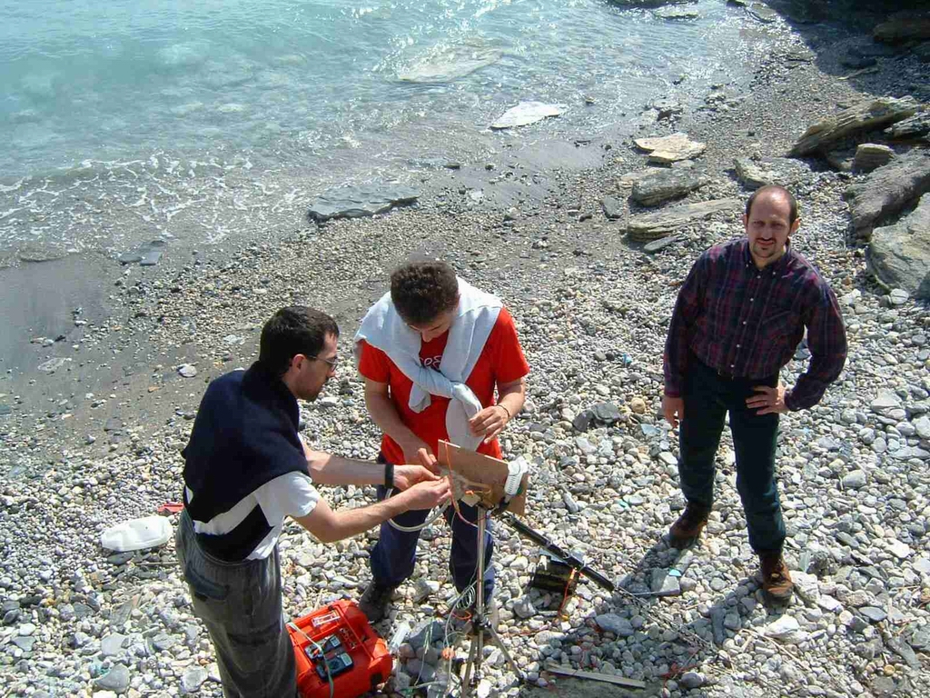 |
Fig. 1 Test of gas sampling system in Vulcano island.
After this procedure a sampling pump has been activated with a flow of 0.85 l/min, the condenser has been cooled with ethylic ether and the condensed fluid has been collected in a flask.
In the second phase of the sampling the valve to the condenser has been closed; in this phase the pump has been turned off and the tap of the caustic soda bottle was slowly opened to sample the fumarolic gases according to the traditional method of Giggenbach. With this procedure two samples have been collected with a sampling time of 8-10 min for each.
In the third phase of the sampling the dry gases have been collected by turning the pump on again and opening the valve. Because of problems due to the small dimentions of the flow-through hole of the valve, which impeded the flow of gas, the valve itself has later been bypassed.
In order to compare the obtained results, samples of gas have also been collected with the traditional methods, both with alkaline bottles and with samplers for dry gases.
Results obtained
Caustic soda bottles: comparison of the analytical results highlighted a marked difference between the RoboVolc samples and those collected with the traditional method. Most evident are the higher H2 concentrations in the samples collected by the RoboVolc. This is to be ascribed almost certainly to hydrogen release by hydrolisis catalyzed by the titanium probe.
| Data | He(ppm) | H2(%) | O2 (%) | N2(%) | C0(ppm) | CH4(%) | |
| RoboVolc | 11.04.03 | 27.7 | 61.2 | 0.16 | 33.9 | 10.8 | 4.87 |
| Trad. Meth | 11.04.03 | 24.1 | 29.7 | <l.d. | 68.8 | 6.15 | 2.7 |
The data of dry gases (Table below) show the presence of air in the sampling system, probably due to a non perfect seal of the flask tap.
| Data | He(ppm) | H2(ppm) | O2 (%) | N2(%) | CH4(ppm) | CO2(%) | |
| RoboVolc | 11.04.03 | <l.d. | 6663 | 11.3 | 46.4 | 594 | 41.7 |
| Trad. Meth | 11.04.03 | <l.d. | 16800 | 1.51 | 7.59 | 1317 | 89.24 |
The results of the isotopic analyses on 13C in the samples collected with both methods do not show marked differences, with values of -3.6±0,1 .
The obtained data allow to highlight some aspects of the sampling system that can be summarized in the following points:
- the system comes up with our expectations. It is therefore possible to collect samples with a reliability comparable with the traditional methods of collection;
- new materials must be tested in order to limit air contamination;
- the titanium probe must be substituted with a new one made of iron or stainless steel, avoiding in any case zinced material;
- the use of ether is to be discouraged due to logistic problems, to its toxicity and its flammability. We think that water can be used instead, together with a small radiator in order to disperse the heat of condensation;
- the teflon valve must have a diameter compatible with the flow of condensed steam collected by the sampling system.
Following the test made at Vulcano, the geochemical sampling system has been improved in accord with the remarks reported.
A water radiator and a pump for the dispersion of the heat of condensation have thus been inserted.
The teflon electrovalve has been substituted by another one with a higher flow.
We used a cilindrical condenser made intentionally to grant impermeability to external air.
Furthermore, the sampling and measuring devices have been inserted into protective boxes made of metal grids; this allows to easily disperse the heat while at the same time allowing a good visibility from the outside and a reasonable protection from collisions.
The final version of the system is composed of five parts:
- probe for gas collection
- systems for sampling of acid gases and condensation of steam
- system for sampling of dry gases and measurement of CO2 content
- device for control, data acquisition and power supply
- probe for the determination of oxygen content
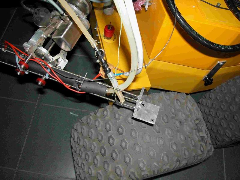
Fig. 2 Gas sampling probe.
The system for the control of and power supply to the samplers and sensors of the geochemical part has been cabled inside the RoboVolc, by housing block 1 on the wrist of the mechanical arm (Fig. 37). In this way it is possible to allow the rotation of the arm apart from the motion of the arm itself, so that the probe can be positioned effectively and precisely in the connection with the sampling funnel placed on the ground surface. This funnel is the part above the ground surface of a sampling pipe which is placed in the sampling site once for all by an operator. This represents an important point for volcanic surveillance, whenever it is necessary to carry out samplings repeatedly in a given site, notwithstanding the area is subject to a potential hazard for the operators.
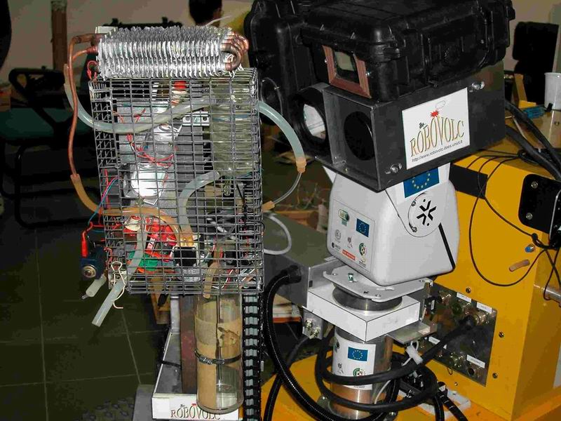
Fig. 3 System for sampling of acid gases and condensation of steam
Block 2 has been installed on the front part of the tower of the arm, so as not to impede the arm movements. This block has been directly connected with the probe end in order to collect the acid gases immediately (Fig. 3). The condensation system has been placed after the flask, inside the same container.
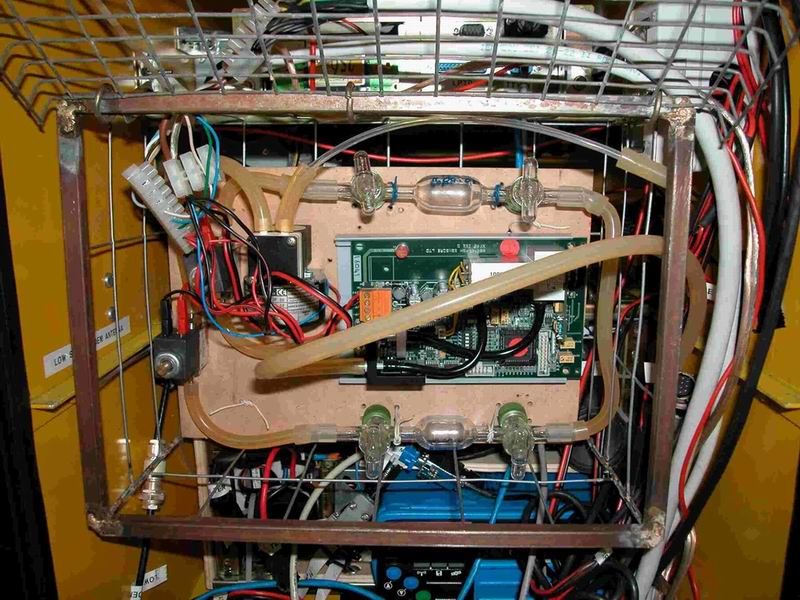
Fig. 4 System for sampling of dry gases and measurement of CO2 content.
Block 3 has been placed inside the robot, immediately behind the door.
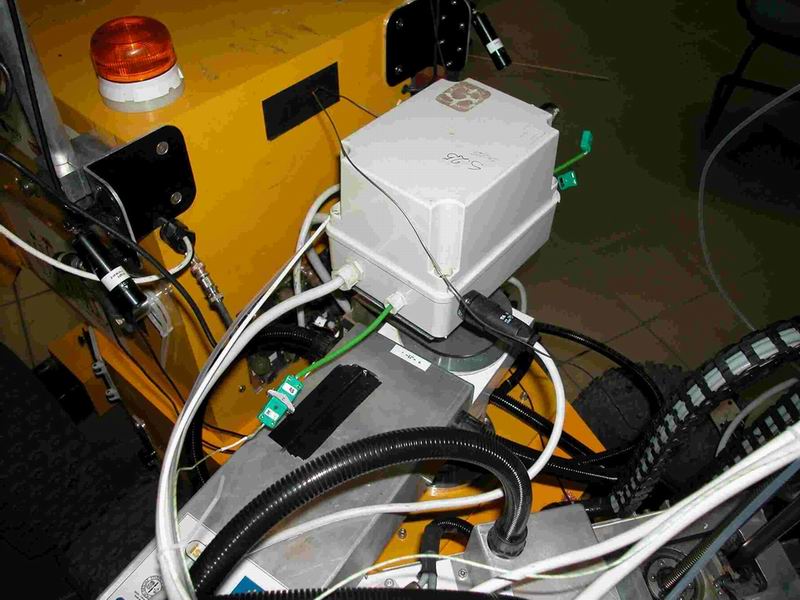
Fig. 5 Device for control, data acquisition and power supply.
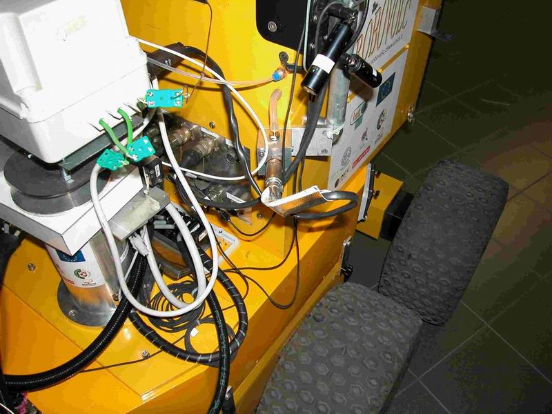
Fig. 6 Oxygen sensor.
Both block 4 and block 5 have been placed outside the robot, on its top. The oxygen sensor of block 5, because it reaches high temperature values during its operation, is the last segment of the gas transport system inside the robot, and is located immediately before the gas exhaust.
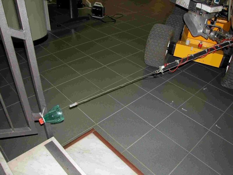
Fig. 7 Test of gas sampling procedure in laboratory.
Several manoeuvring tests have been carried out in the laboratory to check the positioning of the probe in the sampling funnel, and the results were satisfactory.
Conclusions
After the field tests made on the island of Vulcano and the consequent technical improvements adopted, it can be concluded that the sampling system designed for the RoboVolc is able to provide reliable chemical and isotopic data on the fumarolic gases of interest for volcanic surveillance. The system in itself is sufficiently versatile and precise to carry out the gas sampling, provided that a funnel has been previously placed and left constantly in the sampling site. This will allow to reach the primary goal of the project, that is to minimize the exposition of the volcanologists in areas with high volcanic hazard and at the same time to get significant data to be used for volcanic surveillance. Further field tests are necessary to better test the system in its actual version and will be performed in the next period following the end of the project.
